
|
|
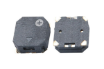
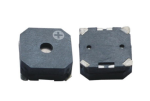
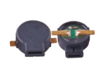
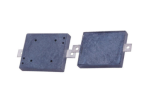
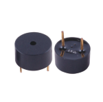
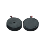
How much is the buzzer drive current? What is the driving current of active buzzerHow much is the buzzer drive current? What is the driving current of active buzzer This is a question that is often mentioned when setting up the circuit during actual operation, generally from a few milliamps to tens of amps. Suqian buzzer manufacturers To understand this issue first to understand the professional classification of the buzzer (our website has a detailed explanation), simply put, the buzzer is divided into active buzzer and passive buzzer, there are sub-piezoelectric buzzer, electromagnetic buzzer, mechanical buzzer, SMD buzzer, etc., which, mechanical buzzer can be classified within the scope of electromagnetic buzzer, because it is a fine category of electromagnetic buzzer, similarly, SMD buzzer is relatively plug-in plug-in buzzer. SMD chip buzzer is relative to the plug-in buzzer, there are also sub-piezoelectric chip buzzer and electromagnetic chip buzzer, the same also has the source and passive points.
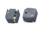
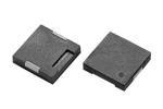
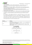
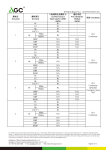
We take a few products in SMD chip buzzer to compare and analyze - under: The passive piezoelectric chip buzzer KS-121203H-0327T and the passive electromagnetic chip buzzer KS-050025F-0304 are the two models to be compared. The KS-050025F-0304 chip buzzer's larger consumption current can reach 100MA, while the KS-121203H-0327T chip buzzer larger is only 3MA, the same are chip buzzer, however, the difference in consumption current is very large. Since the self-excited buzzer is driven by DC voltage, it does not need to use AC signal to drive, but only needs to output the drive level to the drive port and amplify the drive current through the triode to make the buzzer sound. There are two ways for the microcontroller to drive his excited buzzer: one is to drive directly from the PWM output port, and the other is to use the I/O timing to flip the level to generate the drive waveform to drive the buzzer. The PWM output port is used to drive the buzzer directly by outputting a certain square waveform. There are several system registers in the software settings of the microcontroller to set the PWM port output, which can set the duty cycle, period, etc. After setting these registers to generate a waveform that meets the buzzer's required frequency, the PWM output port can output a square waveform of that frequency as soon as the PWM output is turned on, and the buzzer can be driven by this waveform at this time. |